Assist others, participate in conversations, and share your insights with the community.

TonyC
| The reinforcement schedule diagrams for Shell elementsTonyC 2016-04-18 15:11:04 I'm starting this new topic in order to share an interesting technical support case Question: I would like to get further help with regard to the various colour maps that you can choose from in the options list box in the reinforcements window. What do they mean? Answer: Those various options of the list box allow you to view the colour maps on the two faces of the shell element, the amount of necessary reinforcement in the Main/Vertical direction, in Secondary/horizontal direction (for bending or shear) and sum of both directions (bending and shear) (sum of the necessary amount of reinforcement needed in both directions). Take note that the contributions to shear are provided only for reinforced concrete walls. 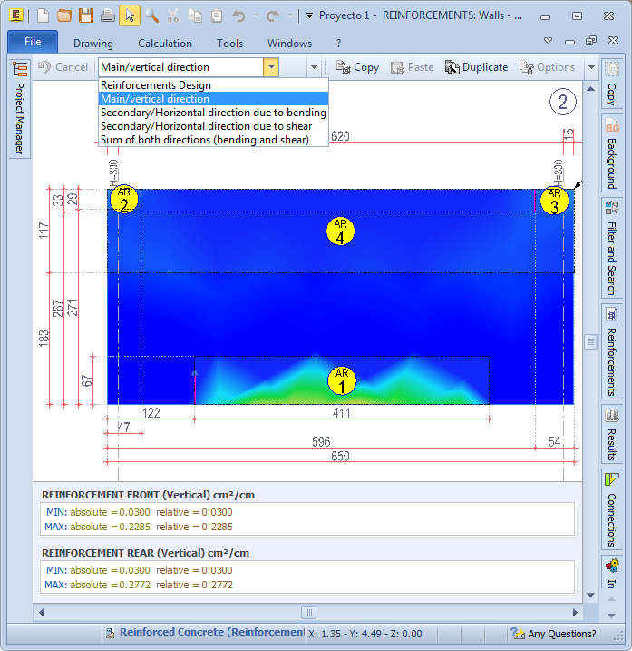  By clicking the Relative Diagram in the Reinforcements window tool-bar, you can see a colour mapping with the extreme colours of the scale ([red] and blue ) respectively coinciding with the maximum and minimum amount of required reinforcement, (in the chosen direction) of the shown shell element. By clicking the Relative Diagram in the Reinforcements window tool-bar, you can see a colour mapping with the extreme colours of the scale ([red] and blue ) respectively coinciding with the maximum and minimum amount of required reinforcement, (in the chosen direction) of the shown shell element. By clicking the button, however, in the Absolute Diagram Toolbar, a color mapping scheme is proposed with ([red] and blue ) respectively shown as the maximum and minimum values of required reinforcement (in the chosen direction) of all shell elements of the project relating to the displayed object type (for example: walls). By clicking the button, however, in the Absolute Diagram Toolbar, a color mapping scheme is proposed with ([red] and blue ) respectively shown as the maximum and minimum values of required reinforcement (in the chosen direction) of all shell elements of the project relating to the displayed object type (for example: walls).The minimum and maximum amount of required reinforcement (in the chosen direction) in the two faces of the shell, are shown in cm²/cm at the bottom left of the window. By moving the cursor on the reinforcement diagram of the front or rear shell element, at the bottom right of the window the following fields are shown: Design (patterned in red), in which the value of necessary reinforcement (Design) in that specific point (and in the chosen direction) is shown and expressed in cm²/cm, ; Structural (patterned in green), in which the current value of reinforcement (structural) in a chosen point (and in the chosen direction) is shown and expressed in cm²/cm. 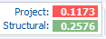 If the operational reinforcement in the specified point is lower than the necessary amount (DESIGN), in order to highlight the need to insert additional reinforcement, the " Operational " Tag is shown in red and the relating reinforcement value is shown in yellow (and always on a green background). 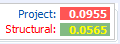 Here's a video showing how to modify and display of the reinforcement diagrams of shell elements: video.accasoftware.com/EN/edilus/id342/index.html?idPLV=6288&autoplay=1 |